
Walter H. Righter (1905 - 1982)Radioplane EnginesDuring WWII, Walter Righter developed a series of small two-stroke cycle engines to power radio-controlled target drones for US Army and Navy gunnery practice. The drones were built by the Radioplane Corporation of Ventura, California (which later became Northrop Corporation - Ventura), Frankfort Sailplane Company of Joliet, Illinois, Globe Manufacturing of Dallas, Texas. The Righter Manufacturing Company was purchased by Radioplane Corporation in May 1945.
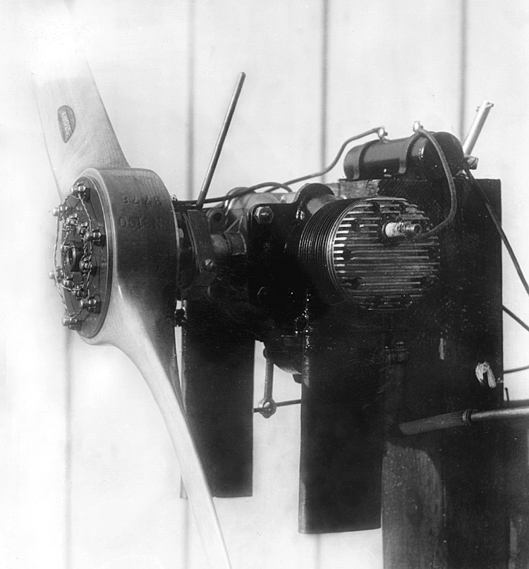
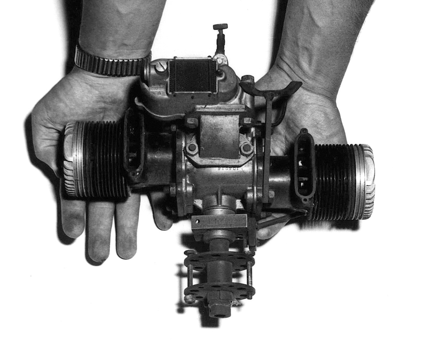
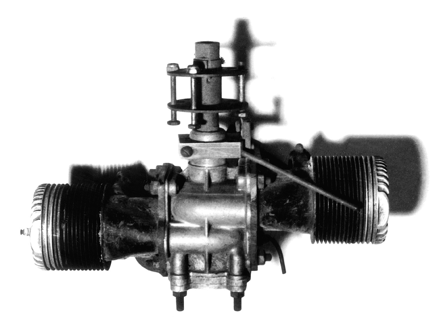
BeginningsIn late 1938 there was a need to create a small lightweight but powerful engine to power the first Denny 'Radioplane' (RP-1) designed and built by Fred Hardy at Denny industries. Walter Righter, who designed and was manufacturing the 'Dennymite' model aero engine for Reg Denny, took up the challenge.Using parts from a 1937 Evinrude 'Fisherman', plus his own more major components, Righter created what I (Russell Naughton) am designating as the 'RP-1 Twin' as a way of defining this engine from a number of other engines described in Righter's notes as a 'small' twin. This engine was also used to power the also 'one-off' developmental 'Radioplane' versions RP-2 and RP-3
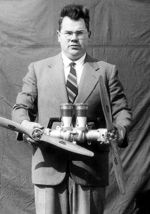
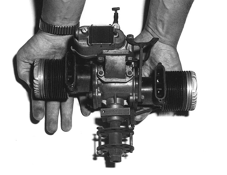 Walter Righter holding his first engine the 'RP-1 Twin' Photo: Dr R.E. Nichol, 1967 (courtesy Jim Dunkin) - Click Image to Enlarge Download a 1500 pixel image
 'RP-1 Twin' Photo: Dr R.E. Nichol, 1967 (courtesy Jim Dunkin) - Click Image to Enlarge Download a 1500 pixel image
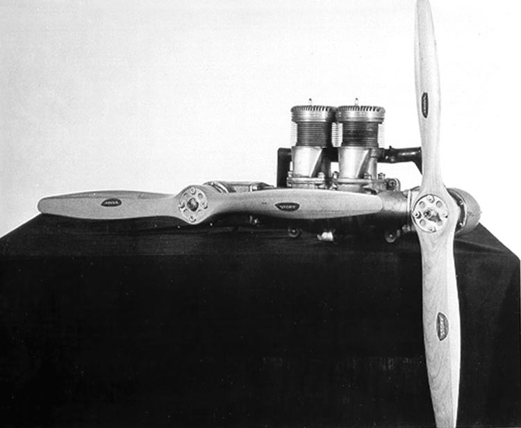
 'RP-1 Twin' Photo: Righter Family Archives - Click Image to Enlarge Download a 1500 pixel image
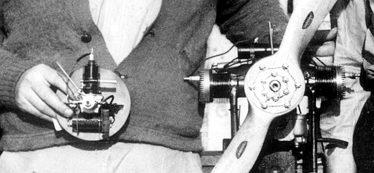 'RP-1 Twin' alongside the first Dennymite .57 model aero engine Photo: Righter Family Archives - Click Image to Enlarge
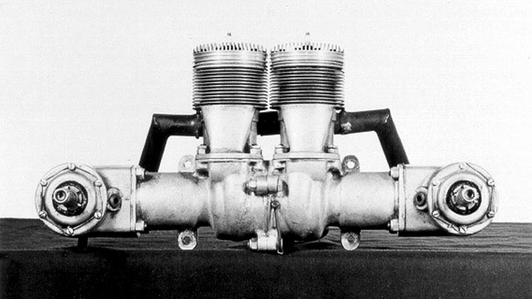
 'RP-1 Twin' Photo: Righter Family Archives - Click Image to Enlarge
 'RP-1 Twin' the hand belongs to financier Don Whittier Photo: Righter Family Archives - Click Image to Enlarge
 'RP-1 Twin' Photo: Righter Family Archives - Click Image to Enlarge
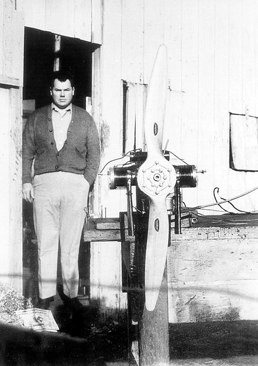
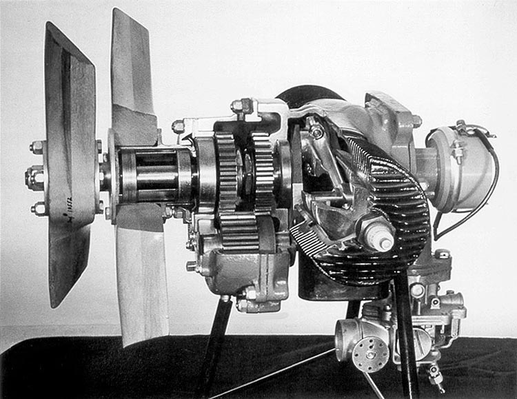
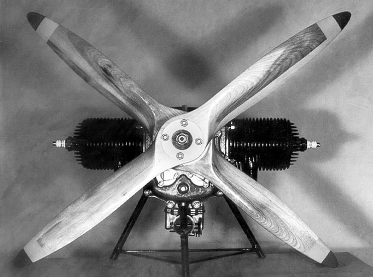
The 'Sidewinder' engine for for the RP-4, c.1939In 1939 Walter Righter developed his so called 'Sidewinder' engine, devised to run two counter rotating propellers. Initially it had its two cylinders (physically) vertically opposed but soon after took up its final form with both cylinders vertically mounted side by sideIt was this engine (four were made) that powered the three RP-4 drones that won Righter (and Reginald Denny's Radioplane Co.) their first contract in May 1939.
 Walt Righter holding the first twin vertical 'Sidewinder' Photo: Righter Family Archives - Click Image to Enlarge
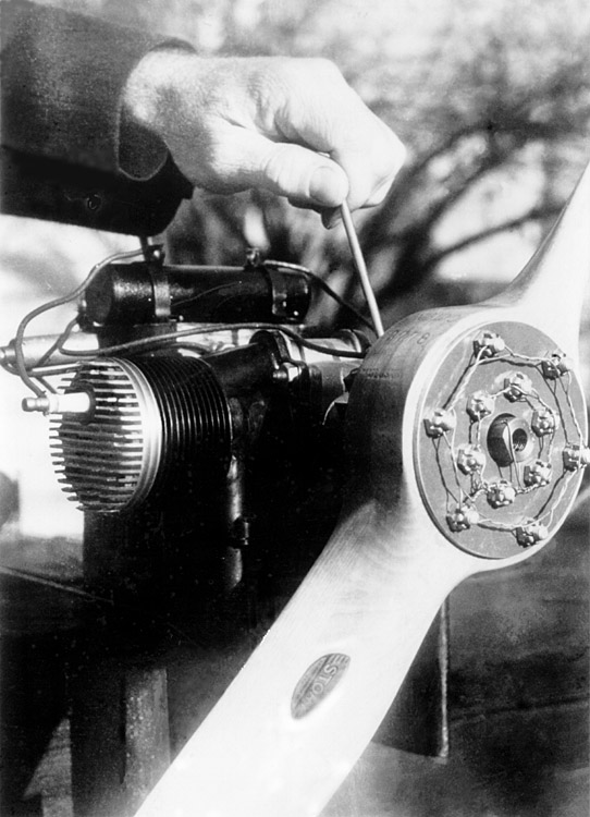
 The "Sidewinder", engine for for the RP-4, c.1939 Photo: Righter Family Archives - Click Image to Enlarge see Radioplane: A Detailed History : Part 1
 The "Sidewinder", engine for for the RP-4, c.1939 Photo: Righter Family Archives - Click Image to Enlarge see Radioplane: A Detailed History : Part 1
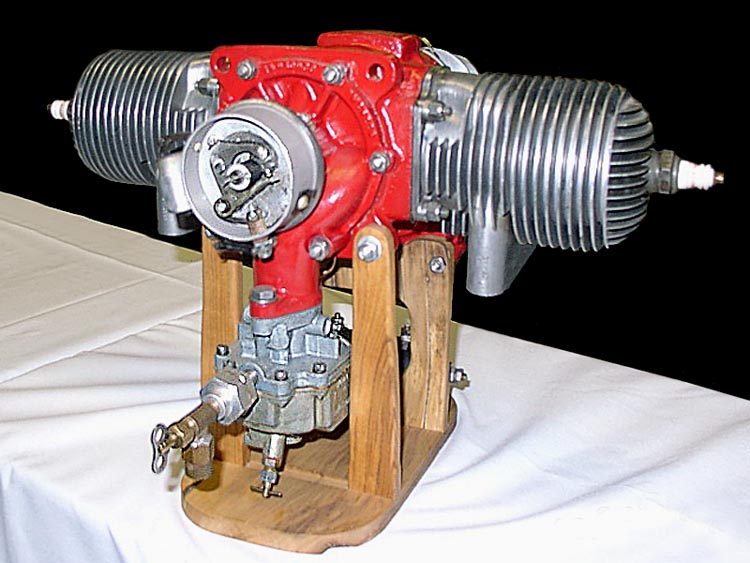
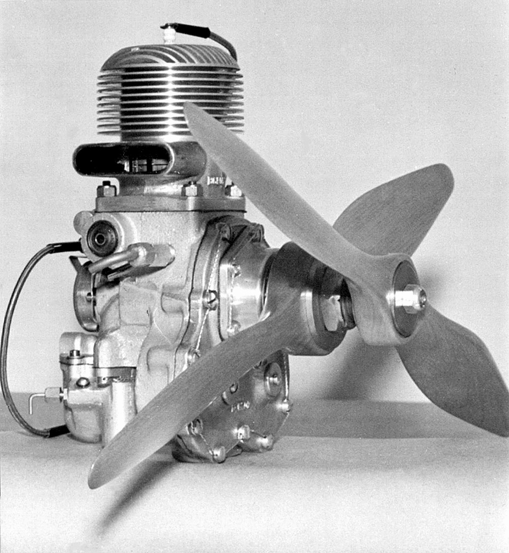
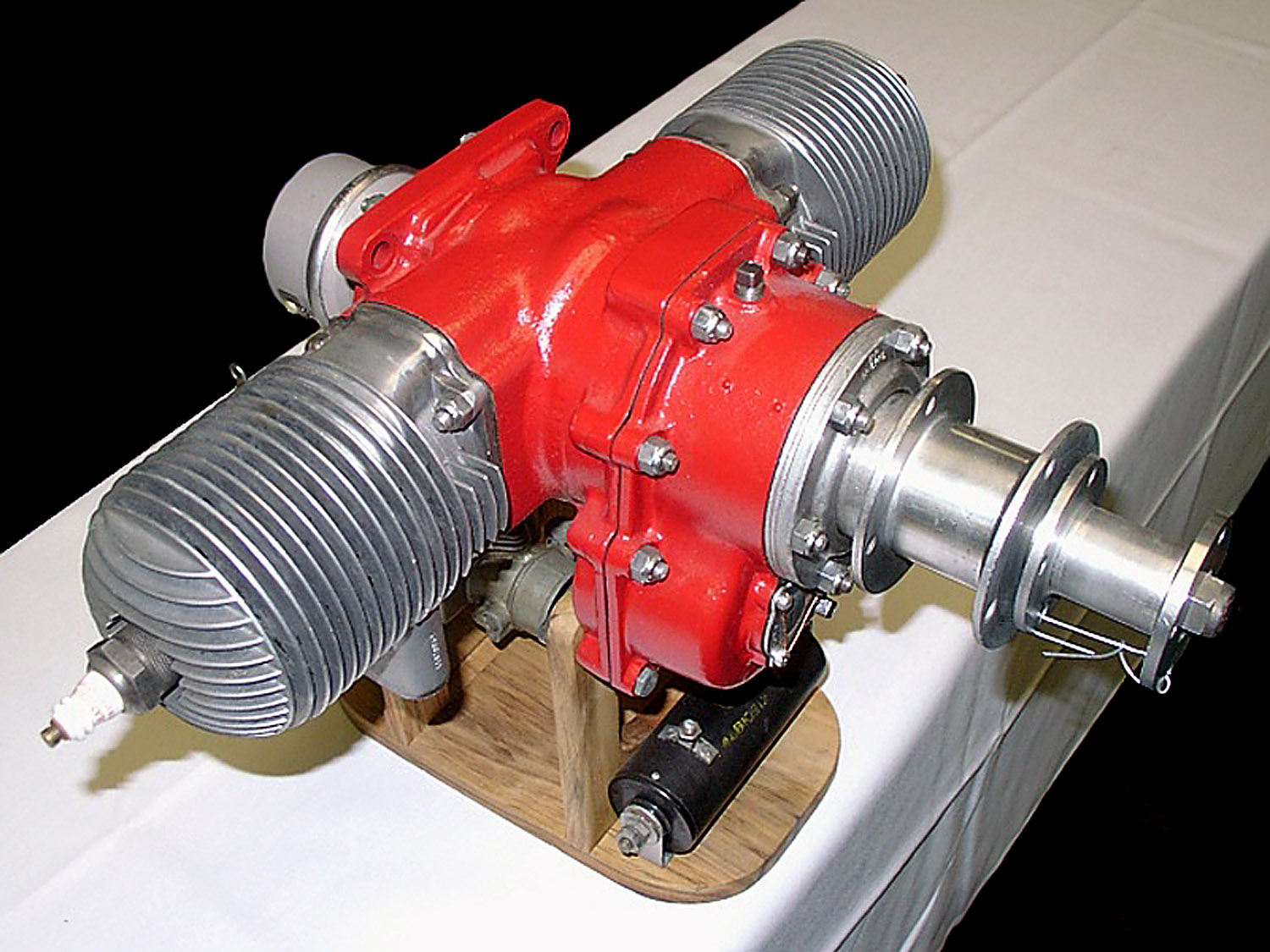
Righter 2-GS-17 / O-15-1, 19412cyl; Model 2-GS-17, Military O-15-1 & -3; 6 to 8.25hp@4000rpm; 1940-1945; Wt = 28#; TC = none.Single-ignition engine with both single-propeller drives and spur-gear counter-rotating propeller drives. Also built by Herkimer Tool and Model Works and McCulloch Manufacturing. AMC; AT3/71; Fahey USAAF; J45-46; MAN5/46. Applications: (US) Frankfort OQ-2A, -2B, & -3 Target Drones; Radioplane A-2, A-2A (OQ-2A), OQ-2B & -3 Target Drones. Ref: http://home.adelphia.net/~aeroengine/Righter.html The 2-GS-17 / O-15-1 was developed to power the next and next most manufactured version of the 'Radioplane', the RP-5 and 5A (Army designation OQ-2 and 2A and Naval designation TDD-1 and TDD-2. Target Drone Denny)
 Righter GS_17, first prototype Photo: Righter Family Archives - Click Image to Enlarge Download a 1000 pixel image
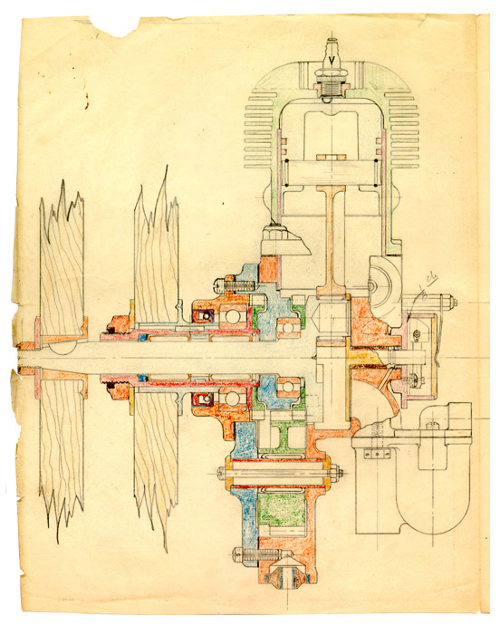 Righter GS-17, original drawing Righter Family Archives - Click Image to Enlarge Download an a4 image [6.2Mb]
 Righter 2-GS-17 Photo: Righter Family Archives - Click Image to Enlarge Download a 1500 pixel image
 Righter 2-GS-17 / O-15-1, twin cylinder prototype Bill 'Wilkie' Wilkins at Don Whittier's home in La Crescenta, CA., Apr/May. 1941 Photo: Righter Family Archives - Click Image to Enlarge
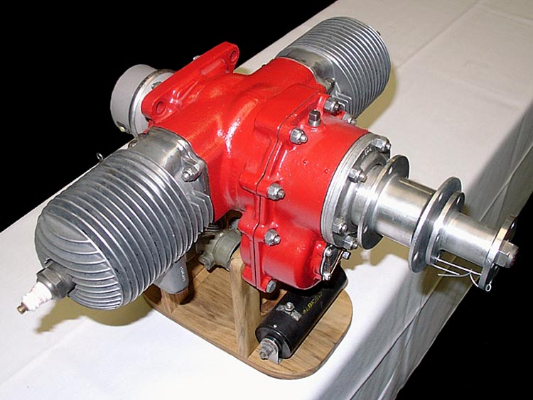
 Righter 2-GS-17 / O-15-1 Most possibly an early production model Photo: Righter Family Archives - Click Image to Enlarge
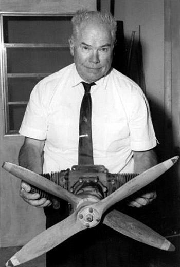 Walter Righter holding what appears to be a 2-GS-17 Photo: Righter Family Archives - Click Image to Enlarge
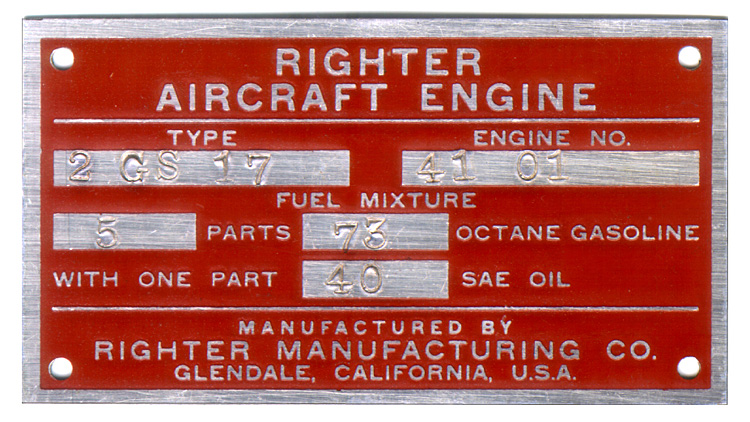 Righter 2-GS-17 nameplate Righter Family Archives - Click Image to Enlarge
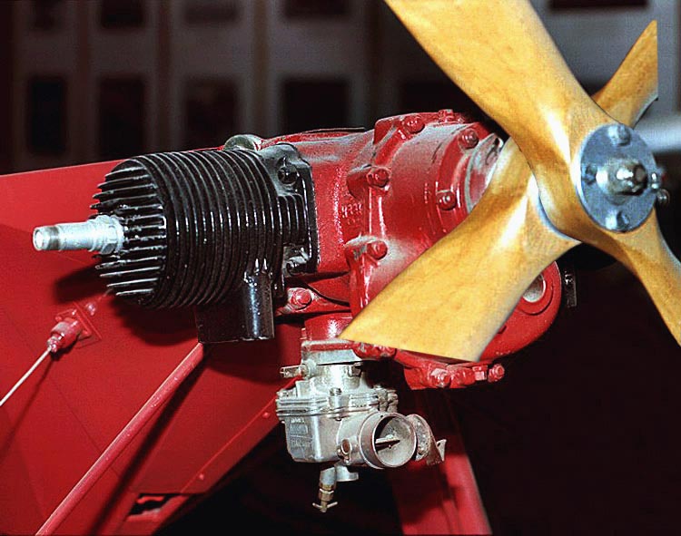 Righter 2-GS-17 / O-15-1 Photo: Jim Dunkin - Click Image to Enlarge
The OQ-2 had counter rotating propellers, push-pull control rods, landing gear, spring leaf tail skid, no wing drag bracing, carried 1.8 gallons of fuel and had level flight speed of 88mph Its successor, the RP-5A (Army OQ-2, Navy TDD-1 Target Drone Denny) also had counter rotating propellers but cable control (to flying surfaces), swivel tail skid, wing drag bracing, carried 1.2 gallons of fuel and had level flight speed of 85mph. The prototype was completed June, 1941 Its successor, the OQ-3, (Navy TDD-2) had heavier steel tube construction with keel, more refinement in installation, a single prop and no landing gear. It's level flight speed was 103 mph. The prototype was completed Dec., 1943. Pete Soule comments re "...wing drag bracing...": "This aeronautical term is not (in my view) very descriptive. It refers to wire bracing inside the wings. From the WWI period the paradigm of wood wings covered with cloth and painted with 'dope' -- an acetate based paint thinned with acetone -- was used for the next score of years. It was replaced by stressed skin metal construction in the following decade for larger and/or expensive aircraft ...but light planes and drones still stuck with the old ways. Inside the wing wires running from the trailing edge to the leading edge and across from one rib to the other were used. Looking on top of the wing they made a pattern of repeating "X" 's criss-crossing between ribs. They added strength to the wing. In a dive the drag force push the wing back and half of these wires are in tension. At high lift the wing is pushed forward and the other half of the wires are in tension -- from this the wire pairs were called "drag and anti-drag wires". The drone may not have been likely to have needed these internal stiffeners and had originally been put in because that was the structural convention."
 Righter 2-GS-17 / O-15-1 Photo: Jim Dunkin - Click Image to Enlarge Download a 1500 pixel image
 Righter 2-GS-17 / O-15-1 Photo: Jim Dunkin - Click Image to Enlarge
|
© Copyright 1999-2005 CTIE - All Rights Reserved - Caution |