
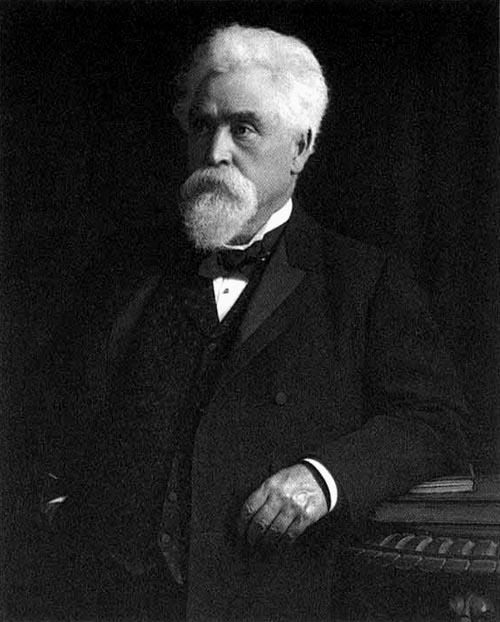
Sir Hiram Maxim (1840 - 1916)
The first powered flight of an Airplane was not, as many suppose, that made by Ader in France in 1897. It was made in the large steam-powered machine designed and built by Sir Hiram Maxim. Well, the Maxim and Ader airplanes were real enough, and they both got off the ground. The catch is that we can't really ask, "Who flew first?" until we agree on what we're willing to call flight.
The 1890s were filled with failed attempts to fly, but Ader and Maxim came as close as anyone to success. Then the Wright brothers made repeated successful flights in 1903, but they rode on so much experience with failure. They were serious, clear-headed men who methodically sorted out all the things that failure had revealed. ©1998 HMHS Hiram Maxim Historical Society, All rights reserved.
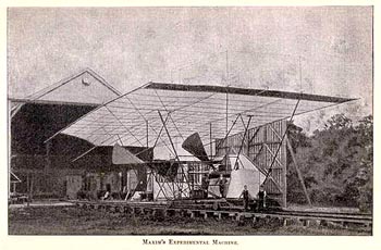
Hiram Maxim's Airplane Hiram Maxim made a fortune from his invention of the Maxim machine gun and he used a good bit of that fortune to explore heavier-than-air flight. Maxim began his aerial experiments at Baldwyns Park, England, in the Mid 1880's which lead to the construction of his enormous biplane. It weighed about 7,000 pounds and had a wingspan of 105 ft.
 Maxim's Aeroplane, 1894 Download a 750pixel image
The machine's two Naptha fired steam engines each produced 180 h.p., and turned two propellers each 17-1/2 feet in diameter. Maxim was wise enough to understand that getting a machine airborne and controlling it once flying were two different things, so his machine was guided by rails, 1800 feet long, which while allowing a degree of 'free' flight, restrained any serious deviation from the straight and narrow and prevented a crash and rebuild from start as had faced so many other experimenters.
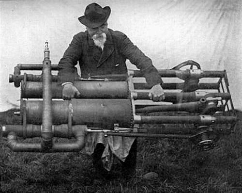 Hiram Maxim and one of his steam engines, c.1884
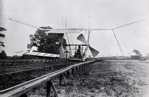
On the Maxim Biplane's third test run, on July 31, 1894, with Maxim and a crew of three aboard, the engines and boilers were coaxed to deliver greater and greater pressure until, when exceeding 42 mph, the whole structure took to the air. It lifted with such force that it broke the restraining track and flew about 200 feet --then crashed and damaged the plane. It was believed that a lifting force of some 10,000 pounds had been generated.
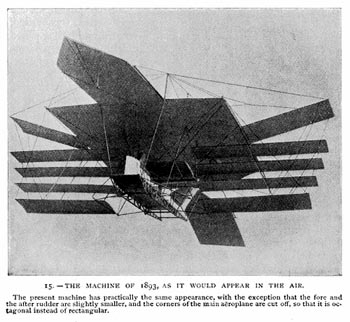 What might have been - An artists impression of the machine in flight
The Development of Aerial Navigation, Sep. 1894
The biplane was subsequently used on a number of occasions to raise funds for charities, rather than raising itself. Maxim lost interest after that. Later he said he'd been first to fly a man off the ground. He wished he'd had one of the new internal combustion engines and had built a smaller plane. Of course, that's what the Wright brothers did nine years later.
Maxim's Propeller testing apparatus Hiram Maxim wrote about an apparatus for testing aeroplane propellers. But this was before there were any aeroplanes. But here is his interest is in flight. He begins with a critical look at French attempts to build powered balloons. He thinks they're a clumsy form of flight.
"Look at birds", he says. "A bird weighs 600 times more than the air it displaces. He shows that a goose in flight never exerts more than a tenth of a horsepower." "Heavier-than-air flight is surely the way to go. Yet birds combine lift and propulsion in the wing, and that's too subtle for us to mimic."Maxim knows we'll have to separate the wing from the propeller. So he's built a central tower with a 32-foot rotating arm to measure the effectiveness of propellers and wing surfaces. A steam engine drives the arm. At the end of the arm is a propeller with a streamlined engine pod and a short section of a wing. That test configuration circles the tower at speeds up to sixty miles per hour, while an electric motor inside the pod drives the propeller. The apparatus offers means for measuring power input to both the propeller and the rotating arm. Maxim's instruments let him separate out lift, thrust, and drag. He finds that, at sixty miles per hour, the propeller might use sixteen horsepower to lift the wing and another 35 horsepower to overcome drag and its own inefficiency. With such detailed preliminary work on flight, Maxim had done superb work on the power inventory of flight, but he hadn't solved the crucial problem of controlling a moving aeroplane. Read a complete essay by Maxim dealing with the above experiments Click here to go the original site or download a compressed set of the 8 pages [1.6 Mb] This files can be de-compressed with the program Stuffit Expander which is available as a free download for both Mac and PC here
The Mastery of the Air
Chapter XVIII A Great British Inventor of Aeroplanes Though, as we have seen, most of the early attempts at aerial navigation were made by foreign engineers, yet we are proud to number among the ranks of the early inventors of heavier-than-air machines Sir Hiram Maxim, who, though an American by birth, has spent most of his life in Britain and may therefore be called a British inventor.
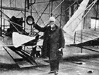 Sir Hiram Maxim and his second Flying Machine, 1909
Perhaps to most of us this inventor's name is known more in connection with the famous "Maxim" gun, which he designed, and which was named after him. But as early as 1894, when the construction of aeroplanes was in a very backward state, Sir Hiram succeeded in making an interesting and ingenious aeroplane, which he proposed to drive by a particularly light steam-engine.
 An early Maxim design, c.1890?
Sir Hiram's first machine, which was made in 1890, was designed to be guided by a double set of rails, one set arranged below and the other above its running wheels. The intention was to make the machine raise itself just off the ground rails, but yet be prevented from soaring by the set of guard rails above the wheels, which acted as a check on it.
 Another design, c.1890?
The motive force was given by a very powerful steam-engine of over 300 horse-power, and this drove two enormous propellers, some 17 feet in length. The total weight of the machine was 8000 pounds, but even with this enormous weight the engine was capable of raising the machine from the ground.
 Maxim's Propellers, 1894
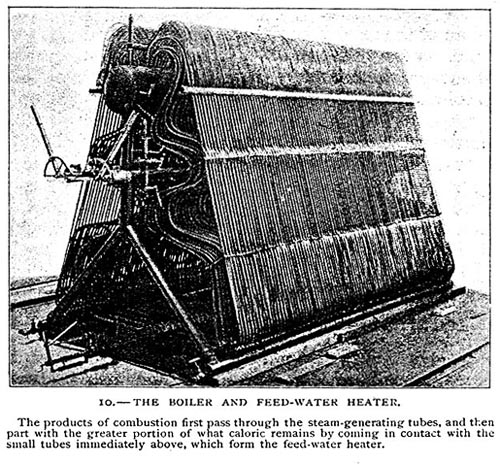 Maxim's Boiler and Feed Water Heater, 1894
For three or four years Sir Hiram made numerous experiments with his aeroplane, but in 1894 it broke through the upper guard rail and turned itself over among the surrounding trees, wrecking itself badly. But though the Maxim aeroplane did not yield very practical results, it proved that if a lighter but more powerful engine could be made, the chief difficulty iii the way of aerial flight would be removed.
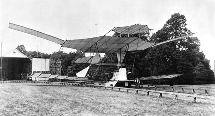
 Maxim's Aeroplane, 1894 Download a 750pixel image
This was soon forthcoming in the invention of the petrol motor. In a lecture to the Scottish Aeronautical Society, delivered in Glasgow in November, 1913, Sir Hiram claimed to be the inventor of the first machine which actually rose from the earth. Before the distinguished inventor spoke of his own work in aviation he recalled experiments made by his father in 1856-7, when Sir Hiram was sixteen years of age. The flying machine designed by the elder Maxim consisted of a small platform, which it was proposed to lift directly into the air by the action of two screw-propellers revolving in reverse directions. For a motor the inventor intended to employ some kind of explosive material, gunpowder preferred, but the lecturer distinctly remembered that his father said that if an apparatus could be successfully navigated through the air it would be of such inevitable value as a military engine that no matter how much it might cost to run it would be used by Governments. Of his own claim as an inventor of air-craft it would be well to quote Sir Hiram's actual words, as given by the Glasgow Herald, which contained a full report of the lecture.
"Some forty years ago, when I commenced to think of the subject, my first idea was to lift my machint by vertical propellers, and I actually commenced drawings and made calculations for a machine on that plan, using an oil motor, or something like a Brayton engine, for motive power. However, I was completely unable to work out any system which would not be too heavy to lift itself directly into the air, and it was only when I commenced to study the aeroplane system that it became apparent to me that it would be possible to make a machine light enough and powerful enough to raise itself without the agency of a balloon. From the first I was convinced that it would be quite out of the question to employ a balloon in any form. At that time the light high-speed petrol motor had no existence. The only power available being steam-engines, I made all my calculations with a view of using steam as the motive power. While I was studying the question of the possibility of making a flying machine that would actually fly, I became convinced that there was but one system to work on, and that was the aeroplane system. I made many calculations, and found that an aeroplane machine driven by a steam-engine ought to lift itself into the air."Sir Hiram then went on to say that it was the work of making an automatic gun which was the direct cause of his experiments with flying machines. To continue the report:
"One day I was approached by three gentle- men who were interested in the gun, and they asked me if it would be possible for me to build a flying machine, how long it would take, and how much it would cost. My reply was that it would take five years and would cost L50,000. The first three years would be devoted to developing a light internal-combustion engine, and the remaining two years to making a flying machine. "Later on a considerable sum of money was placed at my disposal, and the experiments commenced, but unfortunately the gun business called for my attention abroad, and during the first two years of the experimental work I was out of England eighteen months. "Although I had thought much of the internal-combustion engine it seemed to me that it would take too long to develop one and that it would be a hopeless task in my absence from England; so I decided that in my first experiments at least I would use a steam-engine. I therefore designed and made a steam-engine and boiler of which Mr. Charles Parsons has since said that, next to the Maxim gun, it developed more energy for its weight than any other heat engine ever made. That was true at the time, but is very wide of the mark now."Speaking of motors, the veteran lecturer remarked:
"Perhaps there was no problem in the world on which mathematicians had differed so widely as on the problem of flight. Twenty years ago experimenters said: 'Give us a motor that will develop 1 horse-power with the weight of a barnyard fowl, and we will very soon fly.' At the present moment they had motors which would develop over 2 horse-power and did not weigh more than a 12-pound barnyard fowl. These engines had been developed--I might say created--by the builders of motor cars. Extreme lightness had been gradually obtained by those making racing cars, and that had been intensified by aviators. In many cases a speed of 80 or 100 miles per hour had been attained, and machines had remained in the air for hours and had flown long distances. In some cases nearly a ton had been carried for a short distance."Such words as these, coming from the lips of a great inventor, give us a deep insight into the working of the inventor's mind, and, incidentally, show us some of the difficulties which beset all pioneers in their tasks. The science of aviation is, indeed, greatly indebted to these early inventors, not the least of whom is the gallant Sir Hiram Maxim.
A History of Aeronautics
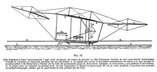
Part IX. Maxim Before turning to consideration of the work accomplished by the Brothers Wright, and their proved conquest of the air, it is necessary first to sketch as briefly as may be the experimental work of Sir (then Mr) Hiram Maxim, who, in his book, Artificial and Natural Flight, has given a fairly complete account of his various experiments. He began by experimenting with models, with screw-propelled planes so attached to a horizontal movable arm that when the screw was set in motion the plane described a circle round a central point, and, eventually, he built a giant aeroplane having a total supporting area of 1,500 square feet, and a wing-span of fifty feet. It has been thought advisable to give a fairly full description of the power plant used to the propulsion of this machine in the section devoted to engine development. The aeroplane, as Maxim describes it, had five long and narrow planes projecting from each side, and a main or central plane of pterygoid aspect. A fore and aft rudder was provided, and had all the auxiliary planes been put in position for experimental work a total lifting surface of 6,000 square feet could have been obtained. Maxim, however, did not use more than 4,000 square feet of lifting surface even in his later experiments; with this he judged the machine capable of lifting slightly under 8,000 lbs. weight, made up of 600 lbs. water in the boiler and tank, a crew of three men, a supply of naphtha fuel, and the weight of the machine itself.
 Maxim's Aeroplane, 1894 Download a 750pixel or 1000pixel image
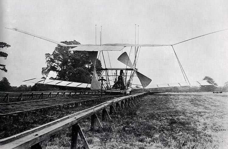
Maxim's intention was, before attempting free flight, to get as much data as possible regarding the conditions under which flight must be obtained, by what is known in these days as 'taxi-ing'--that is, running the propellers at sufficient speed to drive the machine along the ground without actually mounting into the air. He knew that he had an immense lifting surface and a tremendous amount of power in his engine even when the total weight of the experimental plant was taken into consideration, and thus he set about to devise some means of keeping the machine on the nine foot gauge rail track which had been constructed for the trials. At the outset he had a set of very heavy cast-iron wheels made on which to mount the machine, the total weight of wheels, axles, and connections being about one and a half tons. These were so constructed that the light flanged wheels which supported the machine on the steel rails could be lifted six inches above the track, still leaving the heavy wheels on the rails for guidance of the machine.
'This arrangement,' Maxim states, 'was tried on several occasions, the machine being run fast enough to lift the forward end off the track. However, I found considerable difficulty in starting and stopping quickly on account of the great weight, and the amount of energy necessary to set such heavy wheels spinning at a high velocity. The last experiment with these wheels was made when a head wind was blowing at the rate of about ten miles an hour. It was rather unsteady, and when the machine was running at its greatest velocity, a sudden gust lifted not only the front end, but also the heavy front wheels completely off the track, and the machine falling on soft ground was soon blown over by the wind.'Consequently, a safety track was provided, consisting of squared pine logs, three inches by nine inches, placed about two feet above the steel way and having a thirty-foot gauge. Four extra wheels were fitted to the machine on outriggers and so adjusted that, if the machine should lift one inch clear of the steel rails, the wheels at the ends of the outriggers would engage the under side of the pine trackway. The first fully loaded run was made in a dead calm with 150 lbs. steam pressure to the square inch, and there was no sign of the wheels leaving the steel track. On a second run, with 230 lbs. steam pressure the machine seemed to alternate between adherence to the lower and upper tracks, as many as three of the outrigger wheels engaging at the same time, and the weight on the steel rails being reduced practically to nothing. In preparation for a third run, in which it was intended to use full power, a dynamometer was attached to the machine and the engines were started at 200 lbs. pressure, which was gradually increased to 310 lbs per square inch. The incline of the track, added to the reading of the dynamometer, showed a total screw thrust of 2,164 lbs. After the dynamometer test had been completed, and everything had been made ready for trial in motion, careful observers were stationed on each side of the track, and the order was given to release the machine. What follows is best told in Maxim's own words:--
'The enormous screw-thrust started the engine so quickly that it nearly threw the engineers off their feet, and the machine bounded over the track at a great rate. Upon noticing a slight diminution in the steam pressure, I turned on more gas, when almost instantly the steam commenced to blow a steady blast from the small safety valve, showing that the pressure was at least 320 lbs. in the pipes supplying the engines with steam. Before starting on this run, the wheels that were to engage the upper track were painted, and it was the duty of one of my assistants to observe these wheels during the run, while another assistant watched the pressure gauges and dynagraphs. The first part of the track was up a slight incline, but the machine was lifted clear of the lower rails and all of the top wheels were fully engaged on the upper track when about 600 feet had been covered. The speed rapidly increased, and when 900 feet had been covered, one of the rear axle trees, which were of two-inch steel tubing, doubled up and set the rear end of the machine completely free. The pencils ran completely across the cylinders of the dynagraphs and caught on the underneath end. The rear end of the machine being set free, raised considerably above the track and swayed. At about 1,000 feet, the left forward wheel also got clear of the upper track, and shortly afterwards the right forward wheel tore up about 100 feet of the upper track. Steam was at once shut off and the machine sank directly to the earth, embedding the wheels in the soft turf without leaving any other marks, showing most conclusively that the machine was completely suspended in the air before it settled to the earth. In this accident, one of the pine timbers forming the upper track went completely through the lower framework of the machine and broke a number of the tubes, but no damage was done to the machinery except a slight injury to one of the screws.'It is a pity that the multifarious directions in which Maxim turned his energies did not include further development of the aeroplane, for it seems fairly certain that he was as near solution of the problem as Ader himself, and, but for the holding-down outer track, which was really the cause of his accident, his machine would certainly have achieved free flight, though whether it would have risen, flown and alighted, without accident, is matter for conjecture. The difference between experiments with models and with full-sized machines is emphasised by Maxim's statement to the effect that with a small apparatus for ascertaining the power required for artificial flight, an angle of incidence of one in fourteen was most advantageous, while with a large machine he found it best to increase his angle to one in eight in order to get the maximum lifting effect on a short run at a moderate speed. He computed the total lifting effect in the experiments which led to the accident as not less than 10,000 lbs., in which is proof that only his rail system prevented free flight.
Trial of Maxim's Steam Flying Machine On Tuesday, July 31, for the first time in the history of the world, a flying machine actually left the ground, fully equipped with engines, boiler, fuel, water, and a crew of three persons. Its inventor, Mr. Hiram Maxim, had the proud consciousness of feeling that he had accomplished a feat which scores of able mechanics had stated to be impossible. Unfortunately, he had scarcely time to realize his triumph before fate, which so persistently dogs the footsteps of inventors, interposed to dash his hopes. The very precautions which had been adopted to prevent accidents proved fatal to the machine, and in a moment it lay stretched on the ground, like a wounded bird with torn plumage and broken wings. Its very success was the cause of its failure, for not only did it rise, but it tore itself out of the guides placed to limit its flight, and for one short moment it was free. But the wreck of the timber rails became entangled with the sails, and brought it down at once. The machine fell on to the soft sward, embedding its wheels deeply in the grass, and testifying, beyond contradiction, that it had fallen and not run to its position. If it had not been in actual flight, the small flanged wheels would have cut deep tracks in the yielding earth. The Maxim flying machine is a large braced structure formed of steel tubes and wires, and is exceedingly stiff for its weight, which is about 8,000 lb., including men and stores, At its lower part it carries a deck, on which the crew stand, where, also, the boiler, steering wheel, and reservoirs of water and gasoline are mounted. At a height of some 10 feet above the deck come the engines, each of which drives a screw propeller of 17 feet 10 inches diameter and 16 feet pitch, working in air. Above the propellers is the great aeroplane. Smaller aeroplanes project out, like wings, at the sides, the extreme width being 125 feet and the length 104 feet. There are five pairs of wings, as shown in the illustration, but the intermediate three pairs are not always used, and at the time of the accident these were not in place. At that time the area of the aeroplanes, was 4,000 square feet. With all the planes in position, the total area is 5,400 square feet. Forward and aft of the great plane are two steering planes, carried on trunnions at the sides, and connected by wire strands with a drum on the deck. By turning this drum the steering planes can be simultaneously tilted to direct the machine upward or downward, or to keep it on an even keel. The chief interest centers on the boiler, as, unless this be made exceedingly light, it is hopeless to expect that the machine will soar. There is a very close resemblance between the Thornycroft boiler and Maxim's boiler. In each case there are two wing drums, connected by a large number of curved tubes with a steam and water drum, and there are also downcomers to facilitate the circulation. The casing is also made of straight tubes. In the boiler of the flying machine a feed heater is placed over the steam drum, but it is not shown in the engraving. The feed heater is constructed of steel tubes three-sixteenths inch bore and one-twelfth inch thick; the water is pumped through It at a pressure 30 lb. higher than the pressure in the boiler, and is delivered through an injector-like nozzle into the top of the downcomer pipe. The incoming water delivers its surplus energy to the surrounding liquid, creating a rapid and powerful current in the pipe, and consequently maintaining an active circulation in the small tubes in which the steam is generated. The feed pumps are placed on the deck beneath the engines, and are of variable stroke, so as to be adapted to the needs of the boiler. As they work at high speed, the valves are of large diameter-larger than that of the plungers. Pounding is prevented by a rubber bag on the suction and spring pistons on the discharge. The total quantity of water in the boiler only amounts to 200 lb., so that it is necessary that the amount of feed should be accurately adjusted. There is a very ingenious water level indicator. A small pipe is led in a loop from front to back and from back to front of the furnace. It is then taken to the steam and water drum, and led backward and forward through that in the same way, below the water line. The whole is filled with water, and forms a closed circuit having two loops-one in the furnace and one in the water. Now, so long as the upper loop is in the water the pressure does not rise greatly beyond that in the boiler, because the heat taken up in the furnace is conveyed, by the circulation, to the water in the drum. But if the water level falls in the drum, then there is no outlet for the heat; the pressure, consequently, rises most rapidly, and shows itself on a gauge attached to the pipe. By this most ingenious device an open-faced pressure gauge is substituted for the usual gauge glasses. The weight of the boiler, with casing, feed water heater, dome, and uptake, is 904 lb.; with burner and water it is 1, 200 lb. The heating surface is about 800 square feet, and the flame surface 30 square feet. The fuel burned in the boiler is gasoline, of a specific gravity of 72 degrees Baume. It is carried in a copper vessel on deck, and is pumped through a vaporizer into the furnace. The pipe from the pump is led into a vessel having a large gasoline burner beneath it. In this vessel the spirit attains a pressure of 50 lb. on the square inch, and a corresponding temperature, in which condition it is, of course, highly inflammable. The gas which it gives off is conducted by a pipe, passing through the furnace, to a jet, like that of a Bunsen burner, at the front of the furnace, and in rushing through it, induces a powerful draught of air, with which it mixes. The combined charge passes through hollow fire bars, pierced on the upper surfaces with fine holes, and burns in 7,650 separate flames. The arrangement is so powerful that the pressure in the boiler can be raised from 100 lb. to 200 lb. in a minute. The air supply can be regulated at will, while the expenditure of gasoline automatically adapts itself to the needs of the boiler. The pressure of the gasoline vapor acts on a ]ever, which is balanced by a spring. If the feed is greater than the consumption, the pressure on the ]ever puts a pawl in gear with a ratchet wheel, and, through intermediate mechanism, works a block along a slotted arm to reduce the throw of the gasoline feed pumps. If the feed is too small, the opposite effect is produced, and the throw of the pump increased. There are two screws, each driven by a separate compound engine, having cylinders 5.05 inches and 8 inches in diameter by 12 inches stroke. The steam is distributed by means of piston valves having 3 inches stroke, and operated by eccentrics. The exhaust steam is delivered into the air, but Mr. Maxim informs us that he used successfully an air condenser. This seems to be a necessity, because the supply of water would prove a serious load. Even to drive 100 horse power would require some 2,500 lb. of water per hour, which would be a considerable addition to a lengthy trip, especially if undertaken for warlike purposes in a hostile country. To supplement, or replace, the safety valve, by-passes are provided so as to allow live steam to pass directly to the low pressure cylinders. Instead of blowing off into the air, the steam is blown past the high pressure cylinders, and the fall in pressure is made to do work on the exhaust from the high pressure cylinders, drawing the steam from the high pressure cylinders and driving it into the low pressure cylinders. The boiler will make more steam than the engines can take in the usual way. The boiler pressure, when running, is 320 lb. per square inch, giving in the high pressure cylinder a differential pressure of 195 lb. and in the low pressure cylinder 125 lb. The cut-offs are respectively 0.75 and 0.625 of the strokes. In the high pressure cylinder there is a very large clearance, designed to prevent injury from water in case the machine should pitch. The actual horse power delivered to the screws is 363 when the engines are running at 375 revolutions per minute. Of this, we are informed by Mr. Maxim, 150 horse power are expended in slip, 133 horse power in actual lift on the aeroplanes, and 80 horse power in driving the machine, with its frames and wires, through the air. The thrust of the screws, when the machine is moored, is 2,100 lb., and when it is running it is 2,000 lb. We give these figures as they were supplied to us, omitting decimals. The total lift is something over 10,000 lb. at a speed of forty miles an hour and with the aeroplanes making an angle of about 7.25 degrees with the horizontal.
A Magnificent Man and his Flying Machines HIRAM Maxim was considered a crackpot inventor when he began working on his flying machines. No-one really thought his hair-raising schemes would get off the ground. Born in Maine, USA, in 1840, his first job was as a carriage-maker, before he got involved in developing gas machines for lighting. Machinery was his forte and in 1881 he came to England and started work on an automatic machine gun, conducting experiments in a small factory in Hatton Garden. The Prince of Wales showed great interest when he perfected a single-barrelled gun capable of firing 660 rounds a minute, and visited him on-site to see his work. He got through over 200,000 rounds of ammunition in his demonstrations, but this got rather expensive so when he gave one at the Public Hall, Bexleyheath, he used corks instead of bullets. Maxim relocated his works to Crayford in about 1888 and bought a house nearby called Stoneyhurst. He joined forces with Nordenfelt Gun Company of Erith, and opened a new factory as the Maxim-Nordenfelt Gun and Ammunition Company. In 1897 this became Vickers, Sons and Maxim Ltd. All kinds of guns were made there, including the pom-pom quick-firer. The Nordenfelt Tavern at Friday Hill was named after the original firm and is still known as the `pompom'. Maxim had also been working on drawings of a prototype flying machine. He reckoned it would cost £5,000 and take five years to realise his dream, and longer to build an engine light enough to power it. In 1889 he built a large hangar at Baldwyns Park, near Dartford, to experiment with engines and propellers. He laid 1,800ft of track on which to test the flying machine and by 1894 it was ready. The machine comprised a four-wheel platform with a naphtha-fired boiler. Two engines fitted to a tubular steel framework supported the flying surfaces, which in turn powered two twin-bladed propellers. The machine weighed 8,000lbs with a flying surface 120ft long and 104ft wide. Trials did not exactly get off to a flying start. On the third attempt, the machine raced down the track and managed to fly 100ft before a structural failure brought it back to earth. While it achieved a height of just two feet, Maxim's machine was the first to lift off the ground. He subsequently put on a display to raise money for the Bexley Cottage Hospital. People paid five shillings for the privilege of hurtling down the track without taking off. He continued with his testing and in 1901, much to the delight of the people of Dartford and the surrounding area, he was knighted, shortly after being granted British citizenship. His involvement with flying machines declined with dwindling finances, although he did develop a lightweight petrol engine with aeronautical applications and built the ``captive flying machine'' at Crystal Palace. Maxim had by now moved house to Dulwich Common where he designed another flying machine which was subsequently wrecked during trials at Joyce Green. His inventions didn't stop at guns and aviation, however, but were as numerous and diverse as a gold extractor to shoe-heel protectors. He died on November 24, 1916, at home in Streatham and was buried in West Norwood cemetery. Towards the end of his life he was asked about the lack of monuments in his memory, particularly at Baldwyns Park. He replied that the authorities had demonstrated their appreciation by building the largest, finest and best-equipped lunatic asylum in the world there -- now the site of Bexley Hospital. Further Reading Hamilton, James E., The Chronic Inventor: The Life And Work Of Hiram Stevens Maxim, Bexley Libraries and Museums. Ogley, Bob, Kent: A Chronicle Of The Century Volume One (1900-1924), Froglets Publications.
Close Encounters with Sir Hiram Maxim Close encounters with Sir Hiram Maxim?, well not exactly, I must have missed him by some forty odd years. Never the less, our paths seem to have crossed several times. Members of the Exhibition Study Group will know of Sir Hiram Maxim, inventor of the famous Captive Flying Machines installed in the Earls Court Exhibition grounds, the Crystal Palace, also at the fairgrounds at Blackpool and Southport. Hiram Maxim was also the inventor of the rapid firing Machine Gun (for which he was knighted in 1901 when he became a naturalised British subject) and as an aviation pioneer, it was from the latter areas that our paths crossed. Hiram Maxim was born in the small town of Sangerville, Maine in the United States on the 5th of February 1840. Following an uneventful school life he became an apprentice coachbuilder, later on working as a machinist in a Maine factory and then for a short time in shipbuilding. During this time he developed an interest in all things mechanical with an appetite for experimenting on mechanical devices. He became unhappy in America and came to Britain in his late twenties where he settled down at South Norwood. His passion for mechanics continued resulting in several patents for a proposed helicopter and a lighter than air flying machine. It was also the machine gun which became my first encounter with Maxim, during an engineering apprenticeship with Vickers Armstrong Ltd., Crayford, Kent. The Crayford works was originally known as the Vickers Sons and Maxim Works and prior to that as the Maxim Works. Although most of the factory buildings during my time there were constructed in the 1930's there were a few that once formed part of the original 1890's Maxim factory. [...] ...Vickers owned land adjacent to the Crayford Greyhound Track, the Power Samas Shop was a single story building some 60 ft long by 60 ft wide, located at one end was about 400 ft of rough land leading to the front doors, two long iron rails stretched from the doors to the end of this field, approximately 9 ft apart, every 10 ft or so was a giant wooden sleeper, the track finally disappeared into a row of poplar trees which marked the boundary. This building and land was once rented by Hiram Maxim and was where he constructed his first steam powered flying machine which actually lifted off the ground on July 31st 1894 even if only for a brief moment with a height of just a few inches. One of the sleepers tilted during the flight and severed the airscrew causing the flying machine to crash into deep muddy ground. The machine was a write off with a financial loss to Maxim of £25,000. In order to raise capital for his next flying experiment he constructed a small model of his idea for a Captive Flying Machine in his back garden at South Norwood. A selection of the "Gentlemen from the Press" were invited to his home for a demonstration of his new machine on March 4th 1904. The resulting stories in the Times and other newspapers caused a sensation, especially Maxim's announcement that he intended to build a full size contraption for the Earls Court Exhibition and that an even larger version was being designed to thrill the crowds at the Crystal Palace, he further gave a piece of prophetic foresight, in that his experiment would lead to a lighter than air machine that would be of enormous value to this country as a military engine of war. The flying machines were very popular, whizzing joyriders around at speeds of up to 100 mph. Hiram Maxim used one of the gondolas on the Crystal Palace machine to fit flying controls, which gave him much information on the theory of aerodynamics. After several more attempts to build a real flying machine Sir Hiram was overtaken by other pioneers, the Wright Brothers in the U.S.A. Fellow ex patriot, Samuel Franklin Cody in Britain and Louis Bleriot in France. By the time he died in 1916, soldiers on the war fronts were using the weapons of his creation, and real flying machines were engaged in aerial combat. The Crystal Palace Captive Flying Machine remained in service up to 1946 then gradually fell into decay until 1948 when a fire in the motor house destroyed much of the supporting framework, it was finally reduced to scrap in 1949 by the George Cohen 600 Group. My third and perhaps final encounter is through collecting Crystal Palace ephemera and the Exhibition Study Group, whereby I have put together a small collection of aviation related items of events that happened at the Crystal Palace. Hiram Maxim and his flying machine being part of the story. The Vickers factory at Crayford I understand was closed in the 1970's and turned into smaller factory premises, most of the original features have now been demolished. The Maxim aircraft shed was demolished up to the tops of the window levels in the late 1950's and rebuilt as part of a printing works, what was left of the track was also removed at this time.
Sir Hiram Maxim : The Chronic Inventor which in part says, regarding his aviation experiments... Flying Machines Maxim had developed an interest in flight and flying machines as early as 1856, but had not been able to further his ambitions in this field. The move to Crayford resurrected his interest in aviation. Spurred on by two work colleagues, Maxim prepared drawings of a prototype 'flying machine'. He estimated that it would take £5,000 and five years of careful preparatory work to bring this pioneering project to fruition; it would take three years to develop a special engine capable of powering the machine. Maxim needed a new base for the development and testing of his flying machine. It would be possible to build the machine at the Crayford works, but additional space was required for testing and experimentation. Maxim located a new site in Dartford near to the Bexley boundary at Baldwyns Park. Permission was obtained to erect a large hangar which could be used for experimental work on the development of an appropriate engine, propellers and flying surfaces. It was necessary to lay eighteen hundred feet of track on which the flying machine could be run and tested. Work on the machine began in 1891. It was composed of a four-wheeled platform onto which was attached a marine-type boiler made by Thornycroft. The boiler was fired by naphtha, producing steam to a pressure of 320 lbs per sq in. The steam generated was fed to two engines, fitted to the tubular steel framework supporting the flying surfaces. Two twin-bladed propellers, each 18ft in diameter, were attached to the machine; these were designed to propel it along the track. In the interests of stability, the constituent framework extended either side of the machine to line up with a restraining guard rail, located along both sides of the track The whole machine weighed 8,000 lbs, with a flying surface measuring 120 ft long by 104 ft wide.
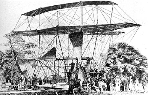
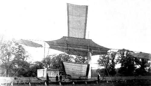 Maxim's machine on its special trackway at "Baldwyns", c.1894. The steam boiler can be seen on the left-hand side of the machine. Picture credit: Dartford museum http://www.dartfordarchive.org.uk
Two initial test runs were conducted. On the third run, on 31st July 1894, the 'Flying Machine', with Maxim at the controls, sped along the trackway. By the time the machine had covered 900 ft of track, it lifted off and covered a further 100 ft before a structure failure in the framework brought it down with a thud, damaging both the machine and the guard rail. Following an inspection of the guard rails, it became clear that the machine had lifted off the ground and had flown! The 'flight' only 100 ft in length, and at a height of only 2 ft, does rather pale into insignificance when compared to modern flight endurances. It did however warrant inclusion in the Guiness Book of Air Facts and Feats as' The largest aeroplane to lift itself off the ground briefly in the nineteenth century.' In November 1894 a modified version of Maxim's record-breaking flying machine took part in a fund-raising event at Baldwyns Park to raise money for Bexley Cottage Hospital. A limited number of people were allowed to ride on the machine on payment of five shillings (25p).
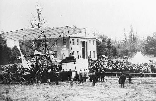 Maxim's Flying Machine in front of the mansion at Baldwyns Park, 1894 Taken at a "flying" exhibition. Spectators are waiting their turn for a ride at five shillings (25p) a time. Picture credit: Dartford museum http://www.dartfordarchive.org.uk
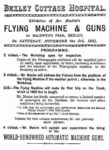 Fund-raising exhibition at Baldwyns Park, 1894. Advertising poster Picture credit: Dartford museum http://www.dartfordarchive.org.uk
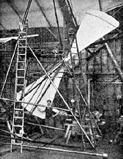
Hiram Maxim became a naturalised British subject and was knighted in 1901. Shortly afterwards he left Baldwyns Park and moved to 'Rycrofts', a house at Dulwich Common. In 1908 he designed a new flying machine, which he had built the following year. This machine looked airworthy, but under test it was beset with problems, so the project was abandoned. The engine of this machine was finally wrecked during trials undertaken at Joyce Green, Dartford in 1910.
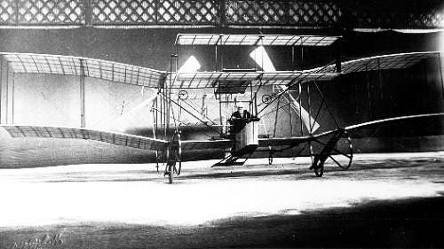 Maxim at the controls of his second Flying Machine, 1909 The photograph was probably taken in the large hangar at Vickers' works, Crayford. The hangar was destroyed by fire in the 1970s. Picture credit: Dartford museum http://www.dartfordarchive.org.uk
Sir Hiram Maxim died on 24th November 1916, bringing to a close a very full and eventful life. Towards the end of his life, he was asked about the lack of monuments to his work at Baldwyns Park. He replied that the authorities had demonstrated their appreciation by building the largest, finest and best-equipped lunatic asylum in the world there!
Further Reading
Aerial Navigation, Apr. 1892 - this is a comment of the Oct. 1991 issue
The Development of Aerial Navigation, Sep. 1894
A New Flying-Machine (By the Inventor), Jan. 1895 These files can be de-compressed with the program Stuffit Expander which is available as a free download for both Mac and PC here
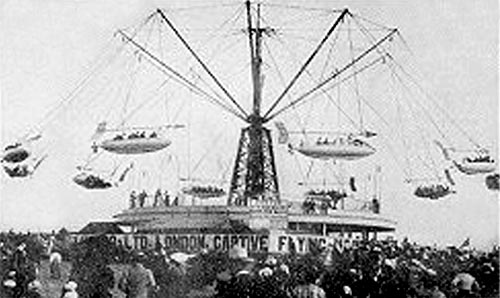
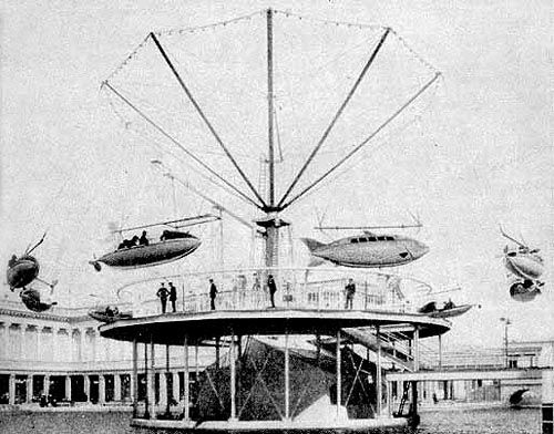
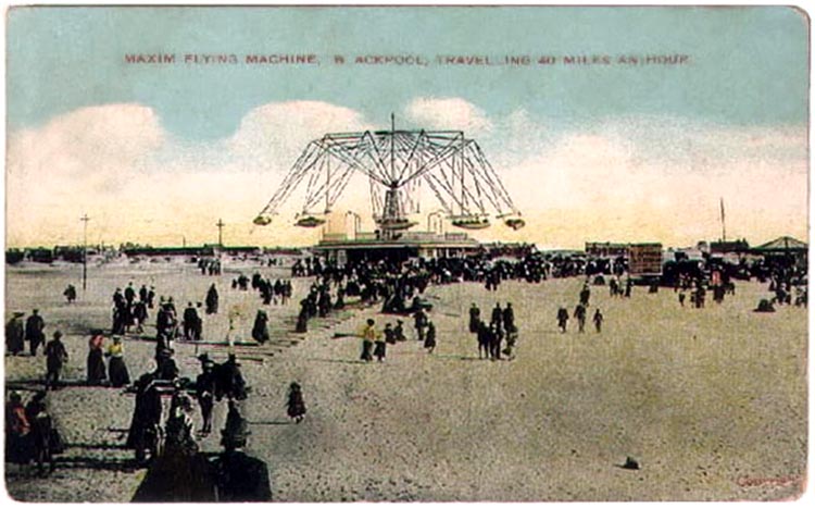
Sir Hiram Maxim's Captive Flying Machines
Pleasure Beach, Blackpool, UK The grandfather of amusement parks, and still the most-visited tourist attraction in the UK. The park, which celebrated its 100th anniversary in 1996, is now most famous for installing multi-million pound state-of-the-art rides. But take a good look around and you will find arguably the best collection of vintage amusement park rides anywhere in the world, all beautifully preserved, and still earning a living.
 Pleasure Beach, Blackpool, UK., 1908 Download a 750pixel image
Vintage attractions [included] Sir Hiram Maxim's Captive Flying Machine : Opened in August 1904, this is the only surviving Flying Machine ride in the world, and the Pleasure Beach's oldest ride. A steel pole 62 feet high supports ten arms, from which hang carriages. As the ride revolves, the carriages spread outwards, hence creating the illusion of flying. This antique machine still operates successfully today amongst the high-tech thrill rides. Designed by Sir Hiram Maxim to raise money for his attempts to be the first man to fly the measured mile. Two others were built. One at Crystal Palace in London and one at Pleasureland, Southport. Both have been demolished.
Pleasure Beach, Blackpool, UK Sir Hiram Maxim's Captive Flying Machine (to give it its full title) opened at the Blackpool Pleasure Beach on August 1, 1904. Maxim (who was born in Maine, USA of French extraction), had been looking for ways to raise extra funding for his experiments with captive flight for the British armed services.
 Pleasure Beach, Blackpool, UK, c. 1900
He was quick to spot the potential for profit by adapting his machine for amusement purposes. Similar rides had opened in locations such as Earls Court, London and in Southport. From an intitial budget of £3,000 the final cost blew out to some £7,000 by completion date however this machine is the only one operating today and is as exhilarating and reliable as I'm sure it was in 1904. You can even see the original machinery on show (Maxim's own and still working!), at the emporium situated under the flying machine. Two 50 hp (37 kw) dc motors are linked by cotton rope drives to 12 foot (3.6m) diameter wheels. These wheels in turn drive the bevel gears which turn the crown wheel attached to the central column..on the column there are the slip rings which transfer an electric current to the ride and give it its decorative lighting. The two original electric motors which are still in use today were made by Lister brothers of Dursley. All the metal castings (which again are original), were made by Robinson and Cook at their Atlas foundry in St. Helens, Merseyside..(once Lancashire.)
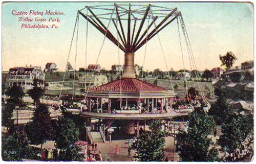
Willow Grove Park, Montgomery County, Pa, USA Willow Grove Park will introduce for the season of 1905 the Sir Hiram Maxim Captive Flying-Machine, and the patrons will be accorded the privilege of the first opportunity in America to indulge in the delights of this newest and most notable product of the genius of the ìEdison of Englandî - Sir Hiram Maxim, inventor of the Maxim gun and other celebrated mechanical achievements.
 View from Administration Avenue Postcard description: 'This is the only official souvenir post card of Willow Grove Park' Instructions in several languages. (J. M. Canfield, Publisher No. 218 - Printed in Saxony - Divided Back Post Card (post 1907 ), Used Postmarked 1910
The first of these ìflying machinesî was erected at Earlís Court, London, only last May. It attracted wide attention, not only by the reason of the fame of its inventor, but also because of its novel character as an amusement enterprise. So pronounced was its immediate success that another machine was put up at the Crystal Palace, London, later in the summer, and it made as great a sensation as the first. Briefly described, the Flying-Machine consists of a central structure, 100 feet high, with ten great extending arms from which are suspended ten ìairshipsî in which the passengers take their novel flight. When all are comfortably settled in the luxuriously fitted ships, the huge arms begin to revolve and the ships move off in widening circles. Under full headway the ships travel more than 600 feet at each revolution, and their own momentum are carried high into the air at the ends of their steel cables. ..the booklet continues to explain that ìsafety is the paramount feature of the ride.î ... the extent of the circle traversed by the ship is such as to do away with the slightest inclination toward dizziness. In fact, the effect on the passenger is the same as though the trip were ìstraight-awayî. There is an utter absence of swinging sensation. ...recommended not only for its entire novelty but also for healthfulness. Exhaustive tests have showed that the swift ride through air results in decided lowering of temperature of passengers... It promises to be one of the unique scenic features of Willow Grove.
Dreamland, Coney Island, Brooklyn, NY, USA Hiram Maxium's Airships ride was located in a grove of vines in Dreamland's central section between Bostock's Arena and Beacon Tower. Its huge rocket-like airships hung from a 150 foot high tower. As they circled it, centrifugal force extended their arc to a 150 foot radius. It cost $75,000 to construct.
 'Maxim's Captive Aeroplane ride circled high above the lagoon' Dreamland, Coney Island, Brooklyn, NY, USA Copyright © Jeffrey Stanton 1997 All Rights Reserved
Patents for Sir Hiram Maxim's Captive Flying Machines
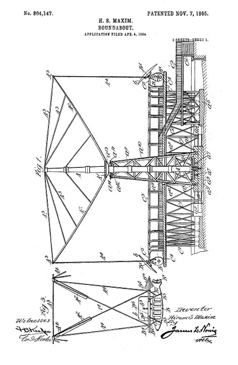 US Patent #804,147, 11/1905, Roundabout [Flying Machine] View the full patent here
 US Patent #831,366, 09/1906, Roundabout [circle swing with tilting axis] View the full patent here
|
© Copyright 1999-2002 CTIE - All Rights Reserved - Caution |